01 / Reliability architecture
What is a Reliability Block Diagram?
A Reliability Block Diagram (RBD) is a graphical representation of how system components contribute to successful operation.
Each block represents a component or subsystem.
The connections between blocks represent the logical relationships required for system success.
Conceptually:
Start
  ↓
Component A
  ↓
Component B
  ↓
End
The system functions only when the required components operate successfully.
By modeling these relationships graphically, engineers can evaluate reliability and availability at the system level rather than focusing solely on individual components.
02 / Reliability architecture
Why RBDs Matter
Reliability Block Diagrams help engineers:
- Visualize complex architectures
- Identify single points of failure
- Evaluate redundancy strategies
- Estimate reliability
- Estimate availability
- Compare alternative designs
- Assess operational risk
Rather than analyzing components independently, RBDs provide a holistic view of system behavior.
03 / Reliability architecture
RBDs within FUSION
The FUSION framework extends traditional Reliability Block Diagrams by integrating both software and hardware reliability information.
Each node may contain:
- Software reliability metrics
- Hardware reliability metrics
- Failure rates
- Repair characteristics
- Availability parameters
Conceptually:
Software Reliability
          +
Hardware Reliability
          ↓
Integrated Node
Multiple integrated nodes can then be combined into larger system architectures.
This approach enables system-level reliability and availability analysis using a unified software–hardware framework.
04 / Reliability architecture
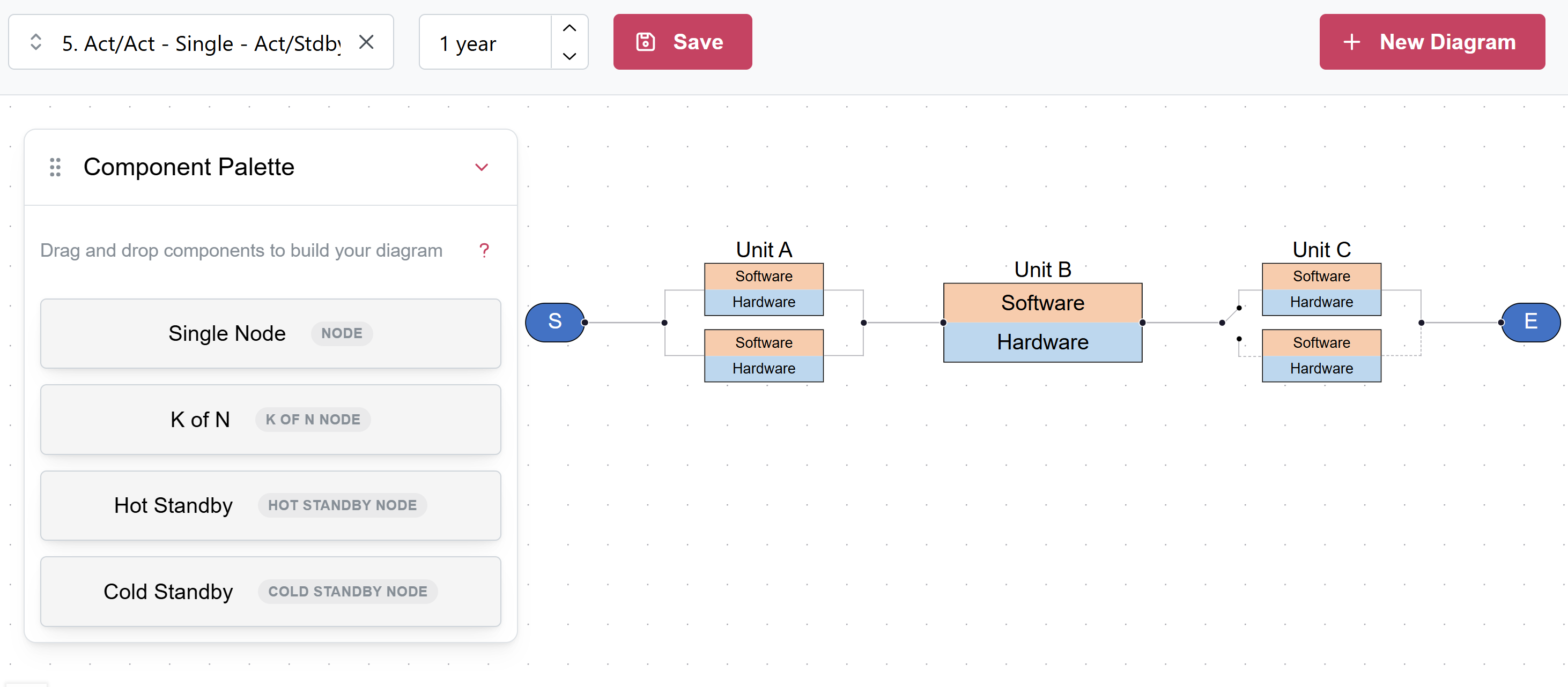
Intelligent Graphical Editor (iGRED)
To simplify RBD construction, FUSION provides the Intelligent Graphical Editor (iGRED).
Rather than manually creating diagrams and deriving reliability equations, engineers can construct systems through an intuitive drag-and-drop interface.
The platform includes a library of preconfigured templates supporting common reliability architectures.
05 / Reliability architecture
Template-Based Modeling
Traditional reliability analysis often requires manual construction of Reliability Block Diagrams and mathematical formulation of system structures.
FUSION simplifies this process through a library of preconfigured architectural templates.
Supported templates include:
- Single Node
- Series Systems
- Parallel Systems
- Active-Active Configurations
- Hot-Standby Systems
- Cold-Standby Systems
- k-out-of-n Architectures
Engineers can rapidly construct complex systems using drag-and-drop operations while preserving the underlying reliability relationships required for accurate analysis. No manual derivation of reliability equations is required.
This approach reduces modeling effort, improves consistency, and enables broader adoption of reliability engineering practices.
06 / Reliability architecture
Common RBD Architectures
Series Architectures
In a series architecture, every component must function successfully for the system to operate.
A → B → C
If any component fails, the system fails.
Series architectures are simple but can be vulnerable to single points of failure.
Parallel Architectures
In a parallel architecture, multiple components provide alternative operational paths.
      A
Start    End
      B
The system continues operating as long as at least one path remains available.
Parallel architectures improve reliability and availability through redundancy.
Active-Active Architectures
In active-active systems, multiple units operate simultaneously.
Benefits include:
- Load sharing
- Improved availability
- Enhanced fault tolerance
These architectures are common in telecommunications and cloud environments.
Active-Standby Architectures
In active-standby systems, one component operates while another remains ready to assume operation immediately after a failure.
Benefits include:
- Improved service continuity
- Simplified failover
- Increased availability
These architectures are frequently used in mission-critical systems.
k-out-of-n Architectures
A k-out-of-n architecture operates successfully when at least k of n components remain operational.
Examples include:
- 2-of-3 systems
- 3-of-5 systems
- 4-of-6 systems
These configurations provide fault tolerance while reducing the impact of individual component failures.
07 / Reliability architecture
Automated Reliability Analysis
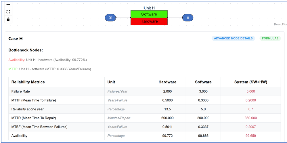
Once an RBD has been constructed, FUSION automatically performs reliability and availability calculations.
Engineers can immediately evaluate:
- Failure Rate
- Reliability
- Mean Time To Failure (MTTF)
- Mean Time To Repair (MTTR)
- Mean Time Between Failures (MTBF)
- Availability
This capability eliminates the need for manual reliability calculations and provides immediate feedback during system design and evaluation.
08 / Reliability architecture
Example Integrated Results
The example shown in Figure 2 illustrates how software and hardware reliability information is combined to generate system-level metrics.
Example outputs include:
- Failure Rate: 5 failures/year
- MTTF: 0.20 years
- Reliability at One Year: 0.7%
- MTTR: 360 minutes
- MTBF: 0.2007 years
- Availability: 99.659%
These metrics are updated automatically as system architectures and component characteristics are modified.
09 / Reliability architecture
Reliability Bottleneck Identification
Complex systems often contain a small number of components that disproportionately affect overall reliability and availability.
FUSION automatically identifies:
- Reliability bottlenecks
- Availability bottlenecks
- Critical software components
- Critical hardware components
- Single points of failure
This capability helps engineers prioritize improvement efforts and focus resources where they will have the greatest impact.
10 / Reliability architecture
From Modeling to Decision Support
Reliability Block Diagrams provide more than visualization.
They support engineering decisions regarding:
- Architecture selection
- Redundancy strategies
- Availability improvement
- Reliability optimization
- Risk reduction
The result is a practical framework for designing resilient software-intensive systems.
11 / Reliability architecture
Supporting Modern Systems
RBD-based analysis is particularly valuable for:
- Open RAN networks
- Cloud-native platforms
- Aerospace systems
- Medical systems
- Semiconductor manufacturing systems
- Industrial automation systems
- Autonomous transportation systems
These environments require an integrated evaluation of software and hardware behavior, as well as operational resilience.
12 / Reliability architecture
Beyond Traditional Reliability Analysis
Traditional reliability tools often focus primarily on hardware behavior.
FUSION extends this perspective by integrating:
Software Reliability
          +
Hardware Reliability
          ↓
System Reliability
          ↓
System Availability
          ↓
Operational Risk
This unified approach provides a more realistic representation of modern software-intensive systems.
13 / Reliability architecture
Foundation for Operational Decision-Making
By combining graphical modeling, integrated software–hardware reliability analysis, automated calculations, and bottleneck identification, FUSION transforms Reliability Block Diagrams into a practical decision-support capability.
Engineers can evaluate alternative architectures, predict operational performance, and improve system resilience before deployment.
14 / Reliability architecture
Looking Ahead
Reliability Block Diagrams provide the architectural foundation for integrated reliability engineering.
The next Methods page introduces System Availability and Operational Risk Assessment, which uses integrated reliability and availability information to evaluate mission success, service continuity, and operational resilience across complex operational environments.
Together, these capabilities form the foundation of the FUSION™ framework for predictive reliability and availability engineering.